Tuesday, February 26, 2013

Day 6: Diodes and More Capacitors

In order to add a DC offset to any Vin, we can simply use a blocking capacitor and build this circuit

Second picture by Hannah

This particular circuit causes a 4 V offset since we are using a 12 V power supply. 
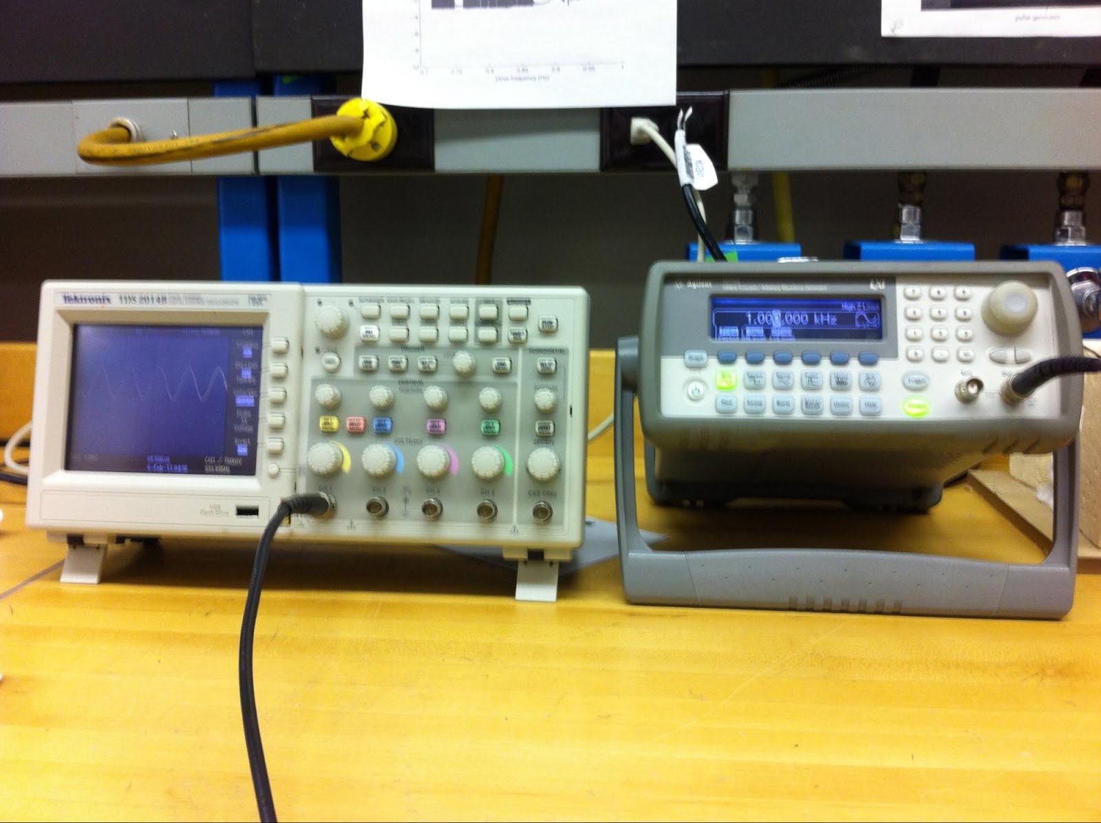


Picture by Hannah

However, at low frequencies, the offset becomes much smaller. In the picture above, the frequency is very high -- 100 kHz. At a lower frequency, like 1 Hz, we merely observe


Picture by Hannah

The offset is still 4V, but because of the similarities of the circuit to a high pass filter, the low frequency wave has been attenuated!


Second picture by Hannah

We can also bring the offset back to 0 V with the circuit above. At 100 kHz, the oscilloscope reads a Vout that looks exactly like the Vin coming out of the function generator. At lower frequencies like 1 Hz, the magnitude of Vout is decreased. So... basically yet another iteration of the high pass filter!


We can figure out the low frequency limit by measuring 3dB. This is, if you recall, the point at which Vout is 70.7% of Vin. So since Vout goes from 1500 mV at 1 MHz to 1050 mV at 11 Hz, the low frequency limit is somewhere in the 11 Hz range.


The next section is on diodes! 

An ohmmeter measures 0.605 V as the forward bias of the diode, and ~5 Mohm as the resistance (though the latter is largely not useful unless we measure a lot of diodes with the same ohmmeter). And of course, we get an infinite voltage if we try to measure the reverse bias.

Now we can build a half wave rectifier!

Second picture by Hannah

We used a variable transformer set to 6 Vac. 

Recall that Vpp = 2 sqrt(2) * Vrms
So, to get a Vrms of 6 V, the power supply should be adjusted until Vpp = 16.8 V

Alternatively, our oscilloscopes will automatically calculate the Vrms and Vpp of a wave.

Picture by Hannah
Yellow is Vin; Blue is Vout

And it lets only positive voltage through, as expected! Of course, we get a Vp > 6 V, since Vp > Vrms


The next task is to build a ripple. 

A 47 μF capacitor is added in parallel with the 2.2 kΩ resistor in the half wave rectifier circuit, being careful to keep the negative end of the capacitor towards ground.


Picture by Hannah
Yellow is Vin; Blue is Vout


As seen above, the measured ΔV = 900 mV

We can calculate ΔV as follows:

ΔV = Vmax (discharge time / (Rload C))
       = 8.4 V (14.8E-3 s / (2.2E3Ω 47E-6 F))
       = 1.2 V
We had to measure discharge time of the capacitor, since it is obviously not discharging for the entire period. Another adjustment could have been measuring the actual Vmax, since Vmax of the output is not the same as that of the input.

Recall that a capacitor has 20% error, so our result has an error of approximately the same order.

Next, we can build a signal diode (aka rectified differentiator)
Second picture by Hannah

By driving the system with a 10 kHz square wave at 20 Vpp (the max our function generator can generate), we ge the following:


Picture by Hannah
Blue shows Vin; Yellow shows Vout

Only the positive derivative is produced!


Without the 2.2 kΩ resistor, the circuit is a mere RC circuit. With the oscilloscope's resistance being 1 MΩ, the time constant is extremely large, so the discharge time is much slower. The 2.2 kΩ resistor therefore draws current through itself, allowing the derivative to correctly be a spike with a short discharge. 


Next, a diode limiter!

Second picture by Hannah

A diode limiter is a wonderful creation that cuts off high voltage. For the following images, we are using a Vin of 100 Hz at the max amplitude of 20 V. 


Pictures by Hannah
Blue is Vin; Yellow is Vout

Since 20 V is much larger than the cut off, we can see clearly how the diode limiter cuts off high voltages.


Picture by Hannah
Blue is Vin; Yellow is Vout

However, the above image has a 100 Hz frequency but only a 1 V amplitude. It does not get cut off very much! This would be very useful if we had an instrument that was damaged by high voltage.

Now we will consider the impedances of test instruments! While we'd like our measurements to not affect the system at all, of course our instruments are not perfect. 


By driving our oscilloscope with a 100 Hz sine wave and the following circuit


We can see that at the attenuation is approximately 1/2.

At the higher frequency of 10 kHz, the attenuation is 1/4.
So, as frequency increases, Vout decreases.

The oscilloscope behaves as a low pass filter!


So, at low frequencies, we should observe the circuit behaving as a simple voltage divider. Since the attenuation was 1/2, we know the resistance of the oscilloscope must be approximately 1 MΩ. This also means the capacitance will be small, somewhere in the 10s of pF.

Recall that the magnitude of the impedance of the capacitor will be 1/ωC. 
At a higher frequency of 10 kHz, the attenuation is 1/4
We can draw the two resistors as one resistor with Rth = 0.5 MΩ.
Now, we can say that for an RC circuit,
Vout = Vin /(1+iωRC)
attenuation = 1/(1+ωRC)
C = (4 - 1) / ωR = 95 pF, using a ω of 2 Pi 10 kHz and R of 0.5 MΩ.

The coaxial cable also has capacitance which makes this capacitance higher than the capacitance of the oscilloscope.

To make the circuit a divide by two attenuator, we must decrease the capacitance of the oscilloscope. This will make the resistance of the scope will dominate even at higher frequencies and still behaves as a voltage divider.

Probes are particularly useful because they increase the impedance.
With a 10x probe where Vout is above, Vout ~ Vin.

Friday, February 22, 2013

Day 5: More Capacitors

We left off with a capacitor integrator.
The next logical step is, of course, a differentiator!
Image from 310 lab manualPicture taken by HannahFollowing basically the same steps as the integrator, the only difference is that Vout is now across the resistor (instead of the capacitor).
In the following pictures, the yellow line indicates the input and the blue line indicates the differentiator output.


Note how the differentiator correctly shifts the sine wave! I think the most interesting is the ramp, as the derivative is the clearest.
Next, we discussed impedance a bit. I think it's easiest to think of as a form of resistance. When the frequency is 0, the impedance R-i/ωC approaches infinity. In contrast, when the frequency is infinity, the impedance approaches R. We also wanted to check what happens to the integrator circuit when the conditions of Vout<<Vin is violated and what happens to the differentiator circuit when 1/ωC<<R are violated. For the integrator circuit, the RC must be decreased; for the differentiator, the RC must be increased. We used a 1000 fold change to make the results very clear.The derivative of the square wave is clearly no longer correct!Then, we built a low pass filter with a 15 kΩ resistor and a 0.01 µF capacitor. This allows low frequencies through the circuit, but high frequencies are not permitted.Mathematically, we want ω3db = 1/RC, which should correspond to a Vout that is 70% of Vin. f3dB = 1/(2πRC) = 1/(2π 15 kΩ 0.01 μF) = 1.1 kHz
The ultimate test is to see if experimentally we will get ~2.1 units of Vout when Vin is 3 units.


And wow! it is 1.2 kHz

The limiting phase shift for an integrator / low pass filter is in phase for low frequencies and 90 degrees out of phase for high frequencies. We will see later that this is the opposite for differentiator / high pass filter.

In phase
Out of phase

We also wanted to look at the 6 dB/octave attenuation (fancy word for reduction) above 3dB.


2 f3dB = 2.4 kHz -> reduced from 15 V to 6.6 V
4 f3dB = 4.8 kHz -> reduced from 15 V to 3.8 V

10 f3dB = 12 kHz -> reduced from 15 V to 1.5 V
20 f3dB = 24 kHz -> reduced from 15 V to 0.8 V

And the phase changes at various frequencies are also as predicted.
f << f3dB -> in phase
f3dB -> 45 degrees out of phase 
f >> f3dB -> 90 degrees out of phase

Why 45 degrees?
f3dB = 1/(ωC) 
Vout = Vin/(1+iωRC) 
1/sqrt(2)  tan-1(1/sqrt(2)) = 45 degrees

Now onto the high pass filter! Basically the exact opposite of the low pass filter -- it uses a differentiator as the base, and permits only low frequencies. We just changed the positions of the capacitor and resistor.
f3dB is once again 1.2 kHz.


The limiting phase shift for a differentiator / high pass filter is in phase for high frequencies and 90 degrees out of phase for low frequencies, with Vin leading.  

Finally, we created a garbage detector. We wanted to measure the "garbage" in the 60 Hz AC power supply. We also did not want to die, so a transformer was used.

The setup

With a high pass filter, the high frequencies can be observed.

And as predicted, it is quite messy!

Thursday, February 14, 2013

Day 4: Transistors and Capacitors!

In this class, we will be using MOSFETs, a type of transistor. Transistors are tiny switches that are activated by a current. Passing a small amount of current through the gate of the transistor allows current to travel from the source to the drain. If no current is on the gate, the no current flows between the source and drain.

This allows us to control a circuit without actually physically flipping a switch. The current supplied by the LogoChip is adequate to turn the MOSFET on.

Image from the 310 lab manual

Picture taken by Hannah

By connecting the motor to the LogoChip as shown, we are able to turn the motor on and off with the LogoChip. Note that a separate battery is used to power the motor.

With this simple program and a light sensor, 

We can get the motor to turn on and off when the light sensor detects light

Video by Hannah

We also looked at capacitors! (I won't go over the details of how capacitors work.)

So we built a capacitance meter! We must try to charge the capacitor only for the linear portion of the charging curve. If it starts to level off, our meter will not work.

Image from 310 lab manual

We followed this circuit diagram...


Wrote this quick program... (It just waits for the capacitance to get to a certain level and then prints the time it took.)

Picture taken by Hannah
Wired it up...

And calibrated it!

A 0.1 μF capacitor and a 100 kΩ resistor corresponds with a 5 ms time. Both an oscilloscope and the PicoBlocks program agreed.

Two 0.1μF capacitors in parallel give a 20 μF capacitance. As predicted, this gives a 10 ms charge time.  

Two 0.1μF capacitors in series give a 5 μF capacitance. As predicted, this gives a 2.5 ms charge time.  

We also built an integrator.

It takes in an input voltage from the function generator and then integrates the input! It probably is better at integration than I am...

Picture taken by Hannah


Picture taken by Hannah

The yellow is the input voltage from the function generator; the blue is the output voltage from the integrator. 

The vertical lines indicate ringing. The output of the function generator (100 kHz) is too high frequency; if the capacitor is given time to discharge, the ringing will go away.

Sunday, February 10, 2013

Day 3: Oscilloscopes!

Although I've played with PicoBlocks before (as earlier posts in this blog show), I've never really spent time with the oscilloscope.

That's about to change!

All the following pictures were taken by Hannah.

First, the oscilloscope was connected to the function generator.


The function generator can generate square waves, triangular waves, and sine waves of varying frequency.


You would think that this square wave has edges that are straight up and down, right? Wrong. If you look at the rising edge closely, you would see this.


It actually takes some time for the voltage to increase! We can quantify the time with something called "risetime," the amount of time it takes to go from 10 to 90% of the wave's max amplitude. This 1 kHz wave has a risetime of 20 ns.

We also played with the oscilloscope for a bit here, to see if for some random input frequency, we could get the oscilloscope to properly display.

The function generator also has a sync out channel, which for a triangle wave would look like this.


Essentially, the sync out channel lets you synchronize measurements. It's always a square wave between 0 and 4 V no matter what your output function is. 

We could also change the output V relative to 0V with the offset function. E.g. if the wave was from 0 to 4 V, an offset of 1 V will change the output wave to between 1 to 5 V. The offset changes the DC component only.

We finished the day off by creating an AC voltage divider


The voltage divider continues to divide voltage, even though the input is alternating! The divided voltage shows the same pattern of alternation as the original input.

A final note, DC coupling will allow AC and DC signal, but AC coupling allows only AC signal.


Tuesday, February 5, 2013

Day 1 and 2: Thevenin's Good Idea

So the week began with wiring up a LogoChip on a breadboard. I followed the steps in the 310 manual rather closely, so I will not repeat the steps taken.

We can get some pretty cool things to happen!


This video shows an LED in a cycle of dimming and brightening. Because this is done by varying the duty cycle, we can observe the voltage across the LED changing as it changes brightness.

Hannah and I easily got the LED to dim when a shadow fell over a photocell, but not to light up when the shadow fell. This is because PicoBlocks has some issues getting multiple numerical operations to occur in a single variable. Our final script looks like this


And when it is run, it looks like this!

Video by Hannah Herde

This brings us to the Thevenin Model.

For any collection of batteries, resistors, and diodes, we can replace it with a single battery and resistor with the Thevenin voltage and resistance respectively. It becomes a black box -- if we draw a box around it and look at the output, we can't tell what's inside!

Then, to find the Thevenin voltage and resistance, we can turn it into a voltage divider. We must vary Rload from 0 Ohm (a simple wire) to 47 Ohm.

With 0 Ohm Rload, Vout = Vth

With 47 Ohm Rload, using the equation Rth = Rload * Vth / Vout - Rload, we can calculate Rth.

Image from the 310 Electronics manual


Black Box Vth Vout Rload Relation of Rload to Rth Rth
Battery Pack 4.3V4.3V 47 Ohm Rload >> Rth ~0 Ohm
LocoChip Output Pin 4.2V 1.6V 47 Ohm Rload > Rth, same order 76 Ohm
Stalled Motor 4.2V 1.3 V 47 Ohm Rload > Rth, same order 105 Ohm