That's about to change!
All the following pictures were taken by Hannah.
First, the oscilloscope was connected to the function generator.
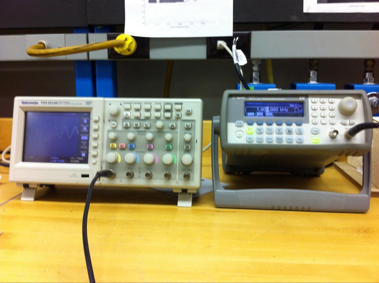
The function generator can generate square waves, triangular waves, and sine waves of varying frequency.

You would think that this square wave has edges that are straight up and down, right? Wrong. If you look at the rising edge closely, you would see this.

It actually takes some time for the voltage to increase! We can quantify the time with something called "risetime," the amount of time it takes to go from 10 to 90% of the wave's max amplitude. This 1 kHz wave has a risetime of 20 ns.
We also played with the oscilloscope for a bit here, to see if for some random input frequency, we could get the oscilloscope to properly display.
The function generator also has a sync out channel, which for a triangle wave would look like this.

Essentially, the sync out channel lets you synchronize measurements. It's always a square wave between 0 and 4 V no matter what your output function is.
We could also change the output V relative to 0V with the offset function. E.g. if the wave was from 0 to 4 V, an offset of 1 V will change the output wave to between 1 to 5 V. The offset changes the DC component only.
We finished the day off by creating an AC voltage divider

The voltage divider continues to divide voltage, even though the input is alternating! The divided voltage shows the same pattern of alternation as the original input.
A final note, DC coupling will allow AC and DC signal, but AC coupling allows only AC signal.
No comments:
Post a Comment